

Ijraset Journal For Research in Applied Science and Engineering Technology
Finite Element Analysis of Connecting Rod using Composite Material
Authors: Ms. Snehal B. Kambale, Prof. M. P. Chopade, Dr. V. S. Goranttiwar
DOI Link: https://doi.org/10.22214/ijraset.2022.42988
Certificate: View Certificate
Abstract
The connecting rod is the intermediate member between the piston and the Crankshaft. Its primary function is to transmit the push and pull from the piston pin to the crank pin, thus converting the reciprocating motion of the piston into rotary motion of the crank. This thesis describes designing and Analysis of connecting rod using composite materials. In this, drawing is drafted from the calculations. In this project connecting rod is replaced by aluminum based composite material reinforced with Boron carbide. And it also describes the modeling and analysis of connecting rod. NX solid modeling software is used to generate the 3-D solid model of Connecting rod. ANSYS software is used to analyze the connecting rod. The main aim of the project is to analysis the stress, strain, deformation of connecting rod by varying material with same geometry.
Introduction
I. INTRODUCTION
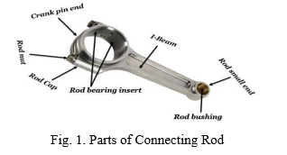
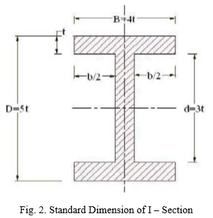
Internal Combustion engine has many parts like cylinder, piston, connecting rod, crank and crank shaft. The connecting rod is very important part of an engine. A connecting rod is the part of a piston engine which connects the piston to the crankshaft. Together with the crank, the connecting rod converts the reciprocating motion of the piston into the rotation of the crankshaft. The connecting rod is required to transmit the compressive and tensile forces from the piston. The connecting rod consists of an I-beam cross-section and is made of forged steel. Aluminum alloy is also used for connecting rods. They are precisely matched in sets of similar weight in order to maintain engine balance. The lighter the connecting rod and piston, the greater the resulting in power and the lesser the vibration because the reciprocating weight is less. The connecting rod carries the power thrust from piston to the crankpin and hence it must be very strong, rigid and also as light as possible. There are two types of connecting rod: H-beam and I-beam or even a combination of the two. These connecting rods are utilized based on the area of application and usage. Figure 1 shows the parts of a connecting rod. The crank end is connected to the crank pin by a shaft. The pin and crank-end pinholes located at the top and bottom ends are machined to allow precise installation of bearings. These openings need to be identical and parallel. The top end of the connecting rod is attached to the piston by the piston pin. As the bottom end of the connecting rod rotates with the crankshaft, the top end is compelled to reverse on and forth on the piston pin. The bushing is essential due to the fact that of the high stress and temperature levels. The bottom hole in the connecting rod is divided to allow it to be secured around the crankshaft. The material is used for the rod is used for the cap which is then screwed by two screws. In the thesis by K. Sudershn Kumar, Dr. K. Tirupathi Reddy, Syed Altaf Hussain, for considering the parameters, the working factor of safety is nearer to theoretical factor of safety in aluminum boron carbide. Percentage of reduction in weight is same in Aluminum 360 and aluminum boron carbide. Percentage of increase in stiffness in aluminum boron carbide is more. Percentage of reducing in stress ALUMINIUM BORON CARBIDE and ALUMNUM is same than CARBON STEEL.
II. HISTORY
The earliest evidence for a connecting rod appears in the late 3rd century AD Roman Hierapolis sawmill. It also appears in two 6th century Eastern Roman saw mills excavated at Ephesus respectively Gerasa. The crank and connecting rod mechanism of these Roman watermills converted the rotary motion of the waterwheel into the linear movement of the saw blades. Sometime between 1174 and 1206, the Arab inventor and engineer Al-Jazari described a machine which incorporated the connecting rod with a crankshaft to pump water as part of a water-raising machine, but the device was unnecessarily complex indicating that he still did not fully understand the concept of power conversion. In Renaissance Italy, the earliest evidence of a − albeit mechanically misunderstood–compound crank and connecting-rod is found in the sketch books of Taccola. A sound understanding of the motion involved displays the painter Pisanello (1455) who showed a piston-pump driven by a waterwheel and operated by two simple cranks and two connecting-rods.
III. METHODOLOGY
A. Problem Statement
The objective of the present work is to design and analyses of connecting rod made of Aluminum Alloy. Steel materials are used to design the connecting rod. In this project the material (Forged steel) of connecting rod replaced with Aluminum Alloy. Connecting rod was created in SIEMENS NX SOFTWARE. Model is imported in ANSYS WORKBENCH 14.0 for analysis. After analysis a comparison is made between existing steel connecting rod viz., An Aluminum Alloy in terms of weight, factor of safety, stiffens, deformation and stress.
B. Mechanical Properties of Carbon Steel, Aluminum 6061, Aluminum Boron carbide
Table 1. Material Properties
|
Sr. No. |
Parameters |
Carbon Steel |
Aluminum 6061 |
Aluminum 6061 BORON Carbide |
|
1 |
Density |
2.7 |
2.68 |
7.87 |
|
2 |
Young’s modules |
70-80 |
195 |
200 |
|
3 |
Poisson’s ratio |
0.33 |
0.32 |
0.29 |
C. Pressure Calculation For 150cc Engine
Suzuki GS 150 R Specifications
Engine type air cooled 4-stroke
Bore × Stroke (mm) = 57×58.6
Displacement= 149.5CC
Maximum Power = 13.8 bhp @ 8500 rpm
Maximum Torque = 13.4 Nm @ 6000 rpm
Compression Ratio= 9.35/1
Density of Petrol C8H18 = 737.22kg/m3 = 737.22E-9kg/mm3
Temperature = 60F = 288.855K
Mass = Density × Volume = 737.22E-9×149.5E3 = 0.11Kg
Molecular Weight of Petrol =114.228 g/mole
From Gas Equation,
PV = MRT,
R = R*/Mw = 8.3143/.114228 = 72.76
P = (0.11x72.786x288.85) / 149.5E3
P = 15.469Mpa =16Mpa
D. Design Calculations for Existing Connecting Rod
IV. DESIGNING OF CONNECTING ROD
A. Designing Procedure of Connecting Rod in SIEMENS NX Software
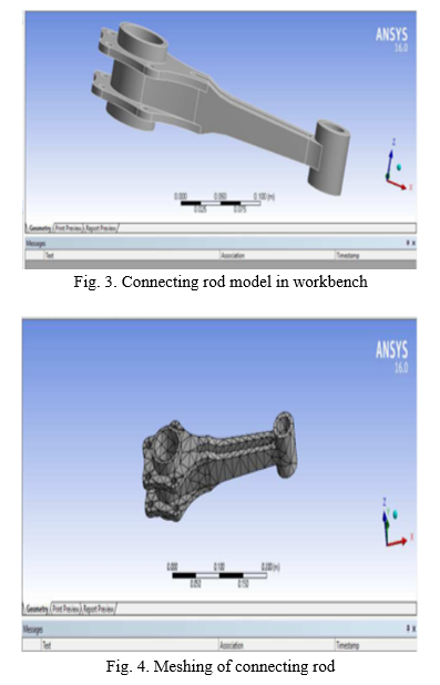
The modeling of the connecting rod is done using NX software. Open NX interface. Initially the inner and outer end i.e. piston end and the crank end diameter are drawn. Draw smaller holes of connecting rod on bog end diameter side. Then the small end and the big end diameter circles are padded respectively. After completion of padding of both big and small the stem of the connecting rod is created. The constructed steam is padded. After finishing the padding of steam pocket is applied to one side of the steam, mirror extent pocket is given in order to pocket the other side of stem. Edge fillets are assigned at the desired locations. Thus the required connecting rod is modeled using NX software.
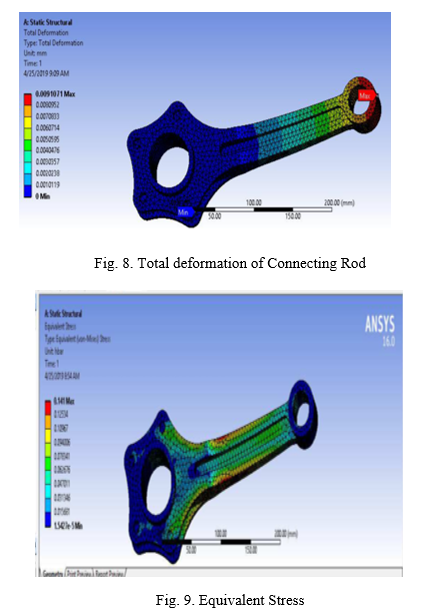
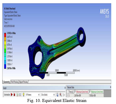
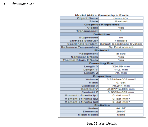
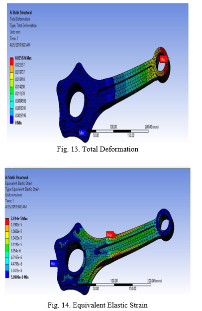
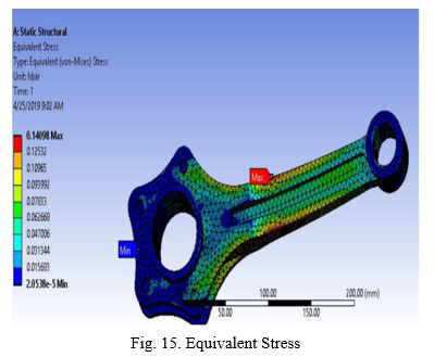
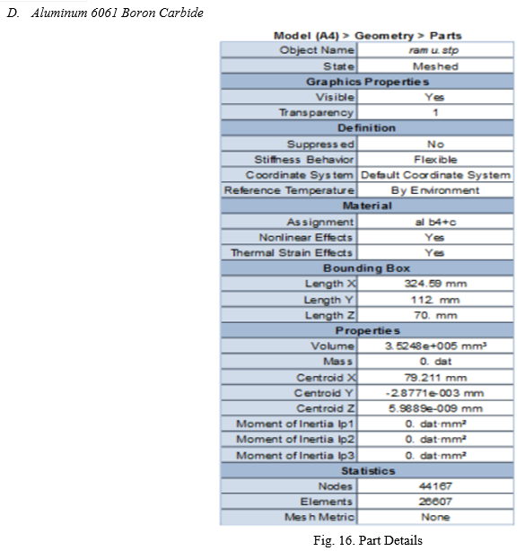
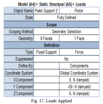
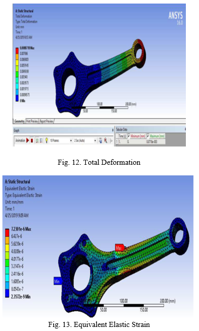
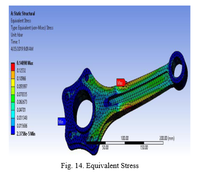
V. ANALYSIS OF CONNECTING ROD
A. Introduction of Finite Element Method
The basic idea in the Finite Element Method is to find the solution of complicated problems with relatively easy way. The Finite Element Method has been a powerful tool for the numerical solution of a wide range of engineering problems. Applications range from deformation and stress analysis of automotive, aircraft, building, defense, and missile and bridge structures to the field of analysis of dynamics, stability, fracture mechanics, heat flux, fluid flow, magnetic flux, seepage, and other flow problems. With the advances in computer technology and CAD systems, complex problems can be modelled with relative ease.
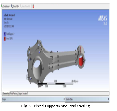
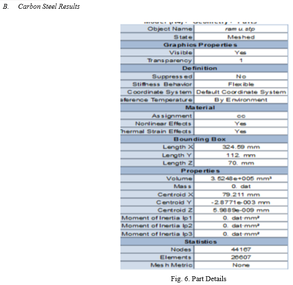
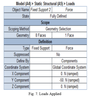
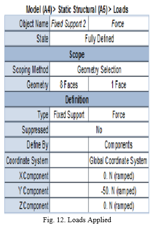
To do the ANSYS we have chosen the workbench of 16 version. Then import the saved connecting rod model to the workbench by saving as part file, as it is easy to import easily for doing meshing and further process. Then go to static structural and insert the data and type of material used for analysis. Go to engineering data and give the density, Poisson’s ratio and young’s modules values.
Next go to geometry and import the part file of connecting which was save before in NX software. Then double click on the model now the actual workbench window opens.
VI. FUTURE SCOPE
From analysis it is observed that the minimum stresses among all loading conditions, were found at crank end cap as well as at piston end. So the material can be reduced from those portions, thereby reducing material cost. For further optimization of material dynamic analysis of connecting rod is needed. After considering dynamic load conditions once again finite element analysis will have to be performed. It will give more accurate results than existing. Design modifications can be done to minimize the weight of the connecting rod and inertia force.
Conclusion
In automotive industries, to achieve reduced fuel consumption as well as greenhouse gas emission is a current issue of utmost importance. To reduce automobile weight and improve fuel efficiency, the auto industry has dramatically increased the use of aluminum in light vehicles in recent years. Aluminum alloy based metal matrix composites (MMCs) with ceramic particulate reinforcement have shown great promise for such applications. These materials having a lower density and higher thermal conductivity as compared to the conventionally used. Weight reduction of up to 50 – 60 % in the systems. Moreover, these advanced materials have the potential to perform better under severe service conditions like higher speed, higher load etc. The objective of the present work is to design and analysis of connecting rod made of Aluminum Alloy. Steel materials are used to design the connecting rod. In this project the material (Forged steel) of connecting rod replaced with Aluminum Alloy. Connecting rod was created in NX 11.0. Model is imported in ANSYS 16.0 for analysis. After analysis a comparison is made between existing steel connecting rod viz., An Aluminum Alloy in terms of weight, factor of safety, stiffens, deformation and stress. The present work aimed at evaluating alternate material for connecting rod with lesser stresses and lighter weight. This work found alternate material for minimizing stresses in connecting rod. FEA analysis performed using ANSYS WORKBENCH 16.0 software for determining stresses & deformation.
References
[1] Pravardhan S. Shenoy and Ali Fatemi, Connecting Rod Optimization for Weight and Cost Reduction, SAE International, 2005. [2] Shahrukh Shamim, Design and Comparative Analysis of Connecting Rod using Finite Element Method, IJERT, Vol. 3 Issue 9, September 2014. [3] K. Sudershn Kumar, K. Tirupathi Reddy, Syed Altaf Hussain “Modeling and analysis of two wheeler connecting rod” International Journal of Modern Engineering Research, Vol.2, Issue.5, Sep-Oct. 2012 pp. 3367- 3371. [4] Suraj Pal, Sunil Kumar “Design evaluation and optimization of connecting rod parameters using FEM,” International Journal of Engineering and Management Research, Vol. 2, Issue 6, December 2012. [5] Vivek C. Pathade, Dilip S. Ingole, “Stress analysis of I.C. engine connecting rod by fem and photo elasticity,” IOSR Journal of Mechanical and Civil Engineering, Volume 6, Issue 1, pp. 117-125, March-April 2013. [6] Goenka, P. K. and Oh, K. P., 1986, “An Optimum Connecting Rod Design Study – A Lubrication Viewpoint,” Journal of Tribology, Transactions of ASME, July 1986, Vol. 108.
Copyright
Copyright © 2022 Ms. Snehal B. Kambale, Prof. M. P. Chopade, Dr. V. S. Goranttiwar. This is an open access article distributed under the Creative Commons Attribution License, which permits unrestricted use, distribution, and reproduction in any medium, provided the original work is properly cited.

Download Paper
Paper Id : IJRASET42988
Publish Date : 2022-05-20
ISSN : 2321-9653
Publisher Name : IJRASET
DOI Link : Click Here
 Submit Paper Online