

Ijraset Journal For Research in Applied Science and Engineering Technology
A Solar Bicycle: Move Towards Green Revolution
Authors: Prof. Shilpee Ghose, Gade Santosh Sarjerao, Saiprasad Nandkumar Shinde, Ajay Mohan Gawade
DOI Link: https://doi.org/10.22214/ijraset.2023.51889
Certificate: View Certificate
Abstract
Introduction
I. INTRODUCTION
A solar bicycle is a bicycle which runs using the electrical energy of battery to run the hub motor which ultimately runs the bicycle. Solar energy is used to charge the battery. Two or more Photovoltaic cells may be used to harness solar energy to generate voltage to charge the battery.
Battery gives the required voltage to the hub motor mounted on the front wheel to run the bicycle. Solar bicycle are not sold generally in our everyday life but there manufacturing can be increased to prevent environmental pollution. These are primarily used as an practical projects and are also sometimes sponsored by government agencies.
There have been many patents on electrical vehicles in different countries and thus electric vehicles are not a very new concept. Utilizing solar energy to charge the battery and combining this concept with the concept of electricity generation pedaling is a new concept and there have been very less research in this regard.
Solar bicycle use photovoltaic cells that convert solar energy into required voltage to charge the battery. There are two types of solar panels that are generally used that is polycrystalline panels and microcrystalline solar panels. The polycrystalline panels are having less efficiency as compared to microcrystalline panels. Polycrystalline panels have efficiency of approximately 15 – 20% while microcrystalline panels have efficiency of 50 -60%.
A. Objectives
- Reduced the physical effort to drive the bicycle,
- Top speed limit up to 35 km/hr and average speed up to 25 km/hr,
- To developed bicycle for the longer distance traveling,
- Cost of bicycle does not exist to Rs20000.
B. Scope of Hybrid Solar Bicycle
- To convert the solar energy to the electrical energy by using solar cells, then converting this electrical energy to mechanical energy by using dc motor to run the bicycle beside the human paddling.
- To find the alternative of fuel.
- To maintain the ecological balance.
- To form the economical bicycle.
II. METHODOLOGY
- Firstly the dc motor was fit on to the rim using spokes.
- The fabrication was carried out keeping in mind the maximum load the motor will be able to withstand. • Various fabrication processes were carried out.
- Tube cutting for the construction of chassis.
- Edge grinding to provide smoother surface finishing.
- Welding to join the tubes to form a stable chassis.
- All the fabricated parts were assembled.
- The controller is powered by batteries which are placed in the control box.
- Controller connects the main electrical components: the throttle and electric brake assembly and also the Hub motor. The throttle sends signal to the controller and based on these signals the controller sends output to the hub motor.
III. SOLID MODELING
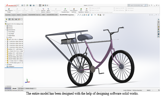
A. Design Parameters
The subject of MACHINE DESIGN deals with the art of designing machine of structure . A machine is a combination of resistance bodies with successfully constrained relative motions which is used for transforming other forms of energy into mechanical energy or transmitting and modifying available design is to create new and better machines or structures and improving the existing ones such that it will convert and control motions either with or without transmitting power. It is the practical application of machinery to the design and construction of machine and structure. In order to design simple component satisfactorily, a sound knowledge of applied science is essential. In addition, strength and properties of materials including some metrological are of prime importance. Knowledge of theory of machine and other branch of applied mechanics is also required in order to know the velocity. Acceleration and inertia force of the various links in motion, mechanics of machinery involve the design.
B. Concept IN M.D.P.
- Consideration in Machine Design
When a machine is to be designed the following points to be considered: -
a. Types of load and stresses caused by the load.
b. Motion of the parts and kinematics of machine. This deals with the
c. Type of motion i.e. reciprocating . Rotary and oscillatory.
d. Selection of material & factors like strength, durability, weight, corrosion resistant, weld ability, machine ability are considered.
e. Form and size of the components.
f. Frictional resistances and ease of lubrication.
g. Convenience and economy in operation.
h. Use of standard parts.
i. Facilities available for manufacturing.
j. Cost of making the machine.
k. Number of machine or product to be manufactured.
2. General Procedure In Machine Design
The general steps to be followed in designing the machine are as followed.
a. Preparation of a statement of the problem indicating the purpose of the machine.
b. Selection of groups of mechanism for the desire motion.
c. Calculation of the force and energy on each machine member.
d. Selection of material.
e. Determining the size of component drawing and sending for manufacture.
f. Preparation of component drawing and sending for manufacture.
g. Manufacturing and assembling the machine.
h. Testing of the machine and for functioning.
3. General Procedure In Machine Design
The general steps to be followed in designing the machine are as followed.
a. Preparation of a statement of the problem indicating the purpose of the machine.
b. Selection of groups of mechanism for the desire motion.
c. Calculation of the force and energy on each machine member.
d. Selection of material.
e. Determining the size of component drawing and sending for Manufacture.
f. Preparation of component drawing and sending for manufacture.
g. Manufacturing and assembling the machine.
k. Testing of the machine and for functioning.
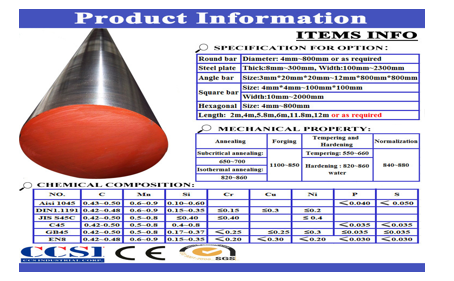
C. EN 10083 C45 steel carbon steel
C45 steel sheet Physico-chemical testing items for products of the plant include tensile test ,hardness test ,impact test ,flattening test ,and chemical composition analysis ,etc .C20,C45 steel pipes are manufactured by cold drawn process.
C45 is a medium carbon steel is used when greater strength and hardness is desired than in the "as rolled" condition. Extreme size accuracy, straightness and concentricity combine to minimize wear in high speed applications. Turned, ground and polished.
SoftAnnealingHeat to 680-710oC, cool slowly in furnace. This will produce a maximum Brinell hardness of 207.Normalizing
Normalizing temperature: 840-880oC/air.HardeningHarden from a temperature of 820-860oC followed by water or oil quenching.TemperingTempering temperature: 550-660oC/air.
C45 steel plate, EN 10083 C45 steel plate, under EN 10083 standard, we can regard C45 steel plate as high carbon steel.C45 steel plate is one mainly of high carbon steel,EN 10083 C45 steel plate is for quenching and tempering. Technical delivery conditions for non alloy steels,these steels are for general engineering purposes
|
C45 EN 10083-2 Number:1.0503 |
Comparision of steel grades |
|
|
JIS G 4051 |
S 45 C |
|
|
DIN 17200 |
C 45 |
|
|
NFA 33-101 |
AF65-C 45 |
|
|
UNI 7846 |
C 45 |
|
|
BS 970 |
070 M 46 |
|
|
UNE 36011 |
C 45 k |
|
|
SAE J 403-AISI |
1042/1045 |
|
Chemical Composition of EN C45 steel
|
Grade |
C(%)min-max |
Si(%)min-max |
Mn(%)min-max |
P(%)max |
S(%)max |
Cr(%)min-max |
|
C45 |
0.42-0.50 |
0.15-0.35 |
0.50-0.80 |
0.025 |
0.025 |
0.20-0.40 |
Mechanical Properties of EN C45 steel
|
Grade |
Condition |
Yield Strength R°(Mpa) |
Tensile Strength Rm (Mpa) |
Elon- gation A5(%) |
Hardness HRC |
Quenching Temperature (?) |
Benda- bility |
Nominal Thickness,t 1.95mm≤t≤10.0mm |
|
|
Rolled |
Annealed |
||||||||
|
C45 |
Rolled Annealed Water-quenched Oil quenched |
460 330 |
750 540 2270 1980 |
18 30 |
58 55 |
820 860 |
Min.reco-mmended Bending radius (≤90°) |
2.0 ×t |
1.0×t
|
D. Properties of steel C45 (1.0503) Properties of steel C45 (1.050
Weldability: Due to the medium-high carbon content it can be welded with some precautions.
Hardenability: It has a low hardenability in water or oil; fit for surface hardening that gives this steel grade a high hardness of the hardened shell.
Why Mild steel C-45 is selected in our project.
- Easily available in all sections.
- Welding ability
- Machinability
- Cuttingablity
- Cheapest in all other metals.
IV. STRUCTURAL DESIGN METHODS
This chapter describes some of the mathematical technique used by designers of complex structures. Mathematical models and analysis are briefly describing and detail description is given of the finite – element method of structural analysis. Solution techniques are presented for static, dynamic & model analysis problems. As part of the design procedure the designer must be analyses the entire structure and some of its components. To perform this analysis, the designer will develop mathematical models of structure that are approximation of the real structure, these models are used to determine the important parameters in the design.
The type of structural model the designer uses depends on the information that is needed and the type of analysis the designer can perform. Three types of structural models are
- Rigid Members: The entire structure or parts of the structure are considered to be rigid, hence no deformation can occur in these members.
- Flexible Members: The entire structure or parts of the structure are modelled members that can deform, but in limited ways. Examples of this member’s trusses, beams and plates.
- Continuum: A continuum model of structure is the most general, since few if any mathematical assumptions about the behaviour of the structure need to be made prior to making a continuum model. A continuum member is based on the full three – dimensional equations of continuum models.
In selecting a model of the structure, the designer also must consider type of analysis to be performed. Four typical analysis that designers perform are:
a. Static Equilibrium: In this analysis the designer is trying to the determine the overall forces and moments that the design will undergo. The analysis is usually done with a rigid members of model of structure and is the simplest analysis to perform.
b. Deformation: This analysis is concerned with how much the structure will move when operating under the design loads. This analysis is usually done with flexible members.
c. Stress: In this analysis the designers wants a very detailed picture of where and at what level the stresses are in the design. This analysis usually done with continuum members.
d. Frequency: This analysis is concerned with determining the natural frequencies and made shape of a structure. This analysis can be done with either flexible members of a structure. This analysis can be done with either flexible members or continuum members but now the mass of the members is included in the analysis.
The subject of MACHINE DESIGN deals with the art of designing machine of structure. A machine is a combination of resistance bodies with successfully constrained relative motions which is used for transforming other forms of energy into mechanical energy or transmitting and modifying available design is to create new and better machines or structures and improving the existing ones such that it will convert and control motions either with or without transmitting power. It is the practical application of machinery to the design and construction of machine and structure. In order to design simple component satisfactorily, a sound knowledge of applied science is essential. In addition, strength and properties of materials including some metrological are of prime importance. Knowledge of theory of machine and other branch of applied mechanics is also required in order to know the velocity. Acceleration and inertia force of the various links in motion, mechanics of machinery involve the design.
V. CONCEPT IN M.D.P.
A. Cnsideration in Machine Design
When a machine is to be designed the following points to be considered: -
- Types of load and stresses caused by the load.
- Motion of the parts and kinematics of machine. This deals with the type of motion i.e. reciprocating. Rotary and oscillatory.
- Selection of material & factors like strength, durability, weight, corrosion resistant, weld ability,machine ability is considered.
- Form and size of the components.
- Frictional resistances and ease of lubrication.
- Convince and economical in operation.
- Use of standard parts.
- Facilities available for manufacturing.
- Cost of making the machine.
- Number of machine or product are manufactured.
B. General Procedure In Machine Design
The general steps to be followed in designing the machine are as followed.
- Preparation of a statement of the problem indicating the purpose of the machine.
- Selection of groups of mechanism for the desire motion.
- Calculation of the force and energy on each machine member.
- Selection of material.
- Determining the size of component drawing and sending for Manufacture.
- Preparation of component drawing and sending for manufacture.
- Manufacturing and assembling the machine.
- Testing of the machine and for functioning.
VI. MAINTENANCE
A. Wear of Working Parts
No equipment in the universe is 100% maintenance free equipment, either it may be human or machine. In Basics Section 2.2.3.2, we discussed the effects of pin wear. When a chain is operating, the outer surface of the pin and inner surface of the bushing rub against one another, wearing little by little.
When a chain is operating, obviously other parts are also moving and wearing. For example, the outer surface of the bushing and inner surface of the roller move against one another. In the case of transmission chain, the roller and bushing wear is less than that of the pin and the inner surface of the bushing because the chance of rubbing is generally smaller. Also, it is easier to apply lubrication between the bushing and roller. The progress of pin-bushing wear is shown in Figure 2.20, in which the horizontal axis is the working hours and the vertical axis is the wear elongation (percent of chain length).
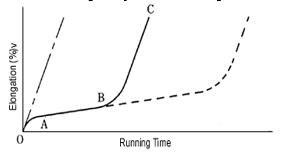
In Figure 2.20, O-A is called "initial wear." At first the wear progresses rapidly, but its ratio is less than 0.1 percent and usually it will cease within 20 hours of continuous operation. A-B is "normal wear." Its progress is slow. B-C is "extreme wear." The limit of ³allowable wear² (the end of its useful life) will be reached during this stage (1.5 to 2.0 percent).
The solid line reflects a case of using chain with working parts that were lubricated in the factory, but were not lubricated again. If you lubricate regularly, the pin and the bushing continue to exhibit normal wear (reflected by the dotted line), and eventually run out their useful life.
If you remove all the lubricants with solvents, the wear progresses along a nearly straight line, and the life of the chain is shortened. The dashed line shows this.
The factors that affect chain wear are very complicated. There are many considerations, such as lubrication, assembly accuracy, condition of produced parts, and the method of producing parts; therefore, wear value can¹t be greatly improved by merely changing one factor. In transmission chain, JIS B 1801-1990 regulates the surface hardness of the pin, the bushing, and the roller (as shown in Table 2.2) to meet the multiple requirements for wear resistance and shock resistance.
Our equipment being compact one requires following maintenance:-
- Due to continuous use of paddle the bearing get worn out causing the vibration. It is required to replace if worn out or broken.
- Periodically check the tension in belt.
- The pins and nut bolts are to be replaced if worn out.
- The welding of different parts should check periodically.
- It is required to colour the equipment periodically.
- Nut bolts and screw should be replaced periodically.
- The broken strips or the angleages should be welded or replaced
- Rope of pulley should replace once in six months.
- Oiling of rotating parts should done once a week.
B. Battery Preservation and Maintenance
There are a variety of parameters which must be kept within certain thresholds to maintain the life of your battery. The most important the depth of discharge (DOD). At a DOD of 80%, the Hawker Genesis battery will deliver about 500 cycles; at 100% DOD, that number decreases to about 400 cycles.
Next in importance to DOD in determining the battery’s cycle life is cycle time. The time allowed for a recharge between discharges is critical to the battery’s life expectancy. Generally speaking, the longer the time allowed for a recharge, the longer the battery’s life expectancy. The preceding paragraph may be better understood if one remembers that a battery is fully recharged when between 105 to 110% of the ampere-hours discharged are put back in the recharge. If the time allowed for a recharge is less, then the current magnitude for a given ampere-hour must be increased. An increase in the charge current can be accomplished only if the charge voltage is also increased. This, in turn, leads to a higher level of overcharge, which speeds up the battery’s ageing process.
Thus, the longer the recharge time, the lower the overcharge rate, and the better it is for the battery. Conversely, the shorter the recharge time, the higher the overcharge and the harsher the condition for the battery.
VII. ADVANTAGES
- Solar energy creates absolutely no pollution. This is perhaps the most important advantage that makes solar energy so much more practical than oil. Oil burning releases harmful greenhouses gases, carcinogens and carbon dioxide into our precious air.
- Solar energy is a completely renewable resource. This means that even when we cannot make use of the sun‘s power because of nighttime or cloudy and stormy days, we can always rely on the sun showing up the very next day as a constant and consistent power source.
- Solar panels and solar lighting may seem quite expensive when you first purchase it, but in the long run you will find yourself saving quite a great deal of money. After all, it does not cost anything to harness the power of the sun. Unfortunately, paying for oil is an expensive prospect and the cost is still rising consistently. Why pay for expensive energy when you can harness it freely?
- Solar powered panels and products are typically extremely easy to install. Wires, cords and power sources are not needed at all, making this an easy prospect to employ.
- Solar power technology is improving consistently over time, as people begin to understand all of the benefits offered by this incredible technology. As our oil reserves decline, it is important for us to turn to alternative sources for energy.
- Oil, which is what most people currently use to power their homes, is not a renewable resource. This means that as soon as the oil is gone, it is gone forever and we will no longer have power or energy. Very little maintenance is required to keep solar cells running. There are no moving parts in a solar cell, which makes it impossible to really hurt them. Solar cells tend to last a good long time with only an annual cleaning to worry about.
- Solar cells make absolutely no noise at all. They do not make a single peep while extracting useful energy from the sun. On the other hand, the giant machines utilized for pumping oil are extremely noisy and therefore very impractical.
- Because an SPV has few moving parts, service requirements are less than for conventional cars.
- Since there is no internal combustion engine and no combustion takes place, there are no emissions.
- Electric vehicles are very quiet. Noise comes only from the electric motors
- Because SPV energy is 100% solar derived, no refueling, in a generic sense, is required. SPV‘s rely on solar power, and the only requirement is that they must be operated in sunshine.
- Added emissions are not produced by power plants, since SPV's do not rely on utility-generated electricity.
- Efficient vehicles have traveled a mile on less energy than a 100-watt light bulb consumes in one hour. (For a gasoline-powered car to achieve comparable efficiency, it would need to get 500 miles per gallon.)
VIII. DISADVANTAGES
- Initial purchase price is high.
- Storage batteries will need to be replaced after about 3-5 years.
- Can't carry more than one passenger.
- Slow speed comparing with other ways of transportation
- Although solar energy is an unlimited resource, it is not always available when it‘s needed—the sun must be shining.
- SPV's that have a built-on PV array differ from conventional vehicles (and most electric vehicles) in size, weight, and shape. The car must be efficiently designed. Lightweight structural materials, such as aluminum or lightweight composites, and low friction components improve performance. They are usually built to carry very little – only one or two people.
- Some SPV‘s use no batteries; others use lightweight silver-zinc batteries. These batteries are expensive and need to be recycled after only a few charging cycles. Nickel-metal-hydride batteries may last up to 100,000 miles, but significantly increase the weight of the vehicle. (Lithium ion battery use is possible, but very expensive.)
- A large amount of surface area is needed on the car to be used solely for solar power PV cells. State-of-theart PV cells are only about 20 percent efficient.
- The primary safety concern with the development of a prototype vehicle, or vehicle altered by hobbyists – as the majority of SPVs are – is that of design and an ability to adequately test the vehicle. If meant for road use, the final design must be road worthy. Proper attention must be paid to all aspects of vehicle design, including steering, suspension, breaks, protection for the driver, proper seatbelts and seating, properly secured motors and batteries, and adequate chassis strength and durability. All prototypes and modified vehicles must be properly tested before operating on-road.
- As with all electric vehicles, lethal levels of electricity may be present in the battery pack, so it should be treated with caution and respect
IX. APPLICATIONS
- Travel for free with the power of the sun.
- Provides free, 'green' transportation for short distances thus it must never plug into a wall socket, or emit any pollutants.
- Charges while at work
- Is cheap, simple, and low maintenance.
- Draws attention to the practical
Conclusion
Solar assisted bicycle is modification of existing bicycle and driven by solar energy. It is suitable for both city and country roads, that are made of cement, asphalt, or mud. This bicycle is cheaper, simpler in construction & can be widely used for short distance travelling especially by school children, college students, office goers, villagers, postmen etc. It is very much suitable for young, aged, handicap people and caters the need of economically poor class of society. It can be operated throughout the year free of cost. The most important feature of this bicycle is that it does not consume valuable fossil fuels thereby saving crores of foreign currencies. It is ecofriendly & pollution free, as it does not have any emissions. Moreover it is noiseless and can be recharged with the AC adapter in case of emergency and cloudy weather. The operating cost per kilometer is minimal, around Rs.0.70/km. It can be driven by manual pedalling in case of any problem with the solar system. It has fewer components, can be easily mounted or dismounted, thus needs less maintenance. The solar bicycle was successfully developed as per the design for disabled community. This bicycle works on solar source and employs BLDC motor to drive the bicycle. The average and maximum speed was obtained as 12.8 kmph and 20 kmph respectively. Various vehicles of same category available in India was compared for different parameter and it was concluded that solar bicycle proved to a complete blessing to the disable community compared to other vehicle using various sources of energy. Due to limited solar energy during cloudy/rainy days provision is made to charge the battery using external electric power source.
References
REFERENCES 1) WORKSHOP TECHNOLOGY – HAZARA CHOUDHARY 2) ELECTRICAL MACHINE DESIGN – A.K.SAWHNEY 3) MACHINE DESIGN – R.S. KHURMI 4) PRODUCTION TECHNOLOGY – BANGA AND SHARMA 5) PRODUCTION PLANNING AND CONTROL – BANGA AND SHARMA 6) METROLOGY & QUALITY CONTROL – R.K.JAIN 7) ists www.google.com 8) www.altavista.com [1] Snehal Bali, Amit Kushwaha, Pratik Dhote, ChetanNandanwar, SandeshUghade, “Fabrication of Solar Powered Bicycle for Handicapped Person”, International Journal for Innovative Research in Science & Technology, Volume 1, Issue 10, March 2015, ISSN (online): 2349-6010 [2] M. ReddiSankar, T. Pushpaveni, V. Bhanu Prakash Reddy, “Design and Development of Solar Assisted Bicycle”, International Journal of Scientific and Research Publications, Volume 3, Issue 3, March 2013 1 ISSN 2250-3153 [3] David Linden, Thomas B. Reddy,“Handbook of Batteries”, 3rd Edition, McGraw-Hill, New York, 2002 ISBN 0-07-135978-8, pp. 24.1 [4] Installation and operating instructions, Amara Raja Batteries, Ref. No. ARB-MAN-Quanta-13-001 [5] ChetanKumaarMaini, “Development of a next generation Electric Car for World Markets”, Journal of EVS 24, Stavanger, Norway, May13-16,2009 [6] Bikewale, TVS, Heavy Duty Super XL, (May, 2016), http://www.bikewale.com/tvsbikes/heavydutysuperxl/
Copyright
Copyright © 2023 Prof. Shilpee Ghose, Gade Santosh Sarjerao, Saiprasad Nandkumar Shinde, Ajay Mohan Gawade. This is an open access article distributed under the Creative Commons Attribution License, which permits unrestricted use, distribution, and reproduction in any medium, provided the original work is properly cited.

Download Paper
Paper Id : IJRASET51889
Publish Date : 2023-05-09
ISSN : 2321-9653
Publisher Name : IJRASET
DOI Link : Click Here
 Submit Paper Online