

Ijraset Journal For Research in Applied Science and Engineering Technology
Studies on Effect of Tool Pin Profiles and Welding Parameters on the Friction Stir Welding of Dissimilar Aluminium Alloys AA5052 & AA6063
Authors: Jujavarapu Sai Ravendra, Palukuri Veerendra
DOI Link: https://doi.org/10.22214/ijraset.2022.41986
Certificate: View Certificate
Abstract
Friction stir welding (FSW) is a solid-state joining process that uses the frictional heat generated by the rotating tool to soften the metals to form the joint. It is an effective technique for joining dissimilar aluminum alloys and finds its application in various fields such as aerospace and automotive industries. FSW process is energy efficient and environment friendly process. This FSW can produce joints with higher mechanical and metallurgical properties. Formerly, FSW was adopted for low melting metals like aluminum alloys. The various FSW parameters play a vital role in determining the quality of the welded joint. The parameters included in the study of different tool pin profiles (circular, pentagon and taper). FEA analysis will be performed for friction stir welding of Aluminum alloy 5052 and AA6063 at different tool pin profiles using ANSYS. This paper mainly focuses on studying the effect of different tool pin profiles on the microstructure and mechanical properties of the dissimilar AA5052 and AA6063 aluminum alloy joints. The weld quality characteristics like microstructure, micro-hardness, and tensile properties of the joints are analyzed and presented for three different tool pin profiles. It is observed from the result that the joint fabricated using three different tool pin profiles exhibits the better mechanical properties when compared to other joints.
Introduction
I. INTRODUCTION
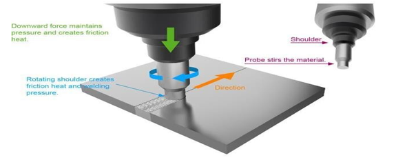
The Friction stir welding (FSW) is a solid-state joining process which means that no molten state is included in joining or welding the respective work piece. The technique which saves energy and is eco-friendly. This joining technique is mostly used to weld aluminum materials in the automobile and aerospace industries. The FSW process in which a tool is used in joining the work piece and is not consumed so it is called a non-consumable tool. A non-consumable rotating tool which is having a pin and a shoulder that is inserted into the adjacent edges of sheets or plates to be joined and moved along the line of joint till the end. This process is considered to be the most significant development in the metal joining process. Also known as a “green” technology due to its energy efficiency, environment friendliness etc..
A. Principle
A non-consumable tool is used to join the adjacent metal sheets which is made up of a pin and shoulder. This tool is used in Friction stir welding and is having two different functions of which the work piece is heated to a temperature in which it is not molten but melted plastically and other function is to weld the work piece it moves along the edges of the work piece so that it is joined. The friction between the tool and the work piece is the heating is achieved by friction between the tool and the work piece and because of the plastic deformation of the work piece. The localized heating softens the material around the pin and shoulder. The tool rotation leads to the movement of material from the front of the pin to the back of the pin. And this completes the welding and a strong solid-state joint is ready.
B. Important Welding Parameters
- Tool Design: Tool design is a very important factor in improving the quality of the work piece. To achieve a good finish in job the tool material should be sufficiently strong, tough and hard-wearing at the welding temperature. The tool should conduct less heat to decrease heat losses and minimizes the damage to the machine’sparts caused by the heat produced. The tool should be highly resistive to oxidation so that there are no traces of rust.
- Tool Speeds: As we know the friction stir welding process is a slower welding process, this is because the cylindrical tool turns on the joint to generate heat, and then moving along the length of the joint transmitting that heat. The probe tool with the cylindrical part rotates within the range of 200 to 2000 rotations per minute (rpm). The traverse rate of the tool along the joint line is between 10 to 500 millimeter per minute (mm/min).
- Tool Tilt: Tool tilt is also an important aspect to get a good quality of weld. It welds the joint in a slightly lean position or tilt position which is about 2 to 4 degrees. The forces applied downwards can affect the joint, so to prevent this condition a tilt is given.
- Plunge Depth: The plunge depth is the total depth till which the shoulder of the tool gets inserted into the metal sheet while the pin penetrates further than the shoulder. It is very important factor to determine the quality of job as the plunge depth needs to be correctly set because it ensures the necessary downward pressure is achieved and also ensure that the tool fully penetrates the weld because if the tool is not inserted to correct depth machine may deflect from its position and on giving excessive plunge depth the job may have pin rubbing marks on it.
II. LITERATURE REVIEW
Sadeesh P et al. [1] used material i.e. 5mm thick plate of AA 2024-T4 (Al-Cu alloy) and AA 6060-T4 (Al-Mg-Si alloy). The plates were cut into rectangular shapes of 100 × 50 mm and the welding had been carried out. Tool used in his study was AISI H13 tool steel, which has high thermal fatigue resistance. The different shape pin profiles used in this work were cylindrical pin, threaded pin, tapered pin, pentagonal pin and stepped pin. The process parameters used were tool shape, rotational speed, traverse speed, tilting angle. AA2024 were placed on the advancing side due to its higher mechanical strength and the tool pin was positioned at center of joint line Optical microscope, scanning electron microscope and energy dispersive spectroscope were used to study microstructure of welded joint. Samples were prepared according to the ASTM E8 standards for tensile test and the tests were carried out at a strain rate of 0.5 mm/min. Micro hardness were carried out at a load of 100gf with dwell time of 10seconds and distance of 0.25mm interval across the welded joint. It was found by studying literature that the rotational speed of 710rpm, traverse speed of 28 mm/min and D/d ratio of 3, for cylindrical pin, were most efficient. Sahu and Pal [2] were carried out experiments by using Taguchi's L18 factorial design of experiment. Grey rational analysis was used for optimizing processes parameters. Percentage effect to find invidual process parameter on the weld quality was measured. They used AM20 Magnesium alloy to form pentagon but joint. Process parameters were used tool rotation speed, welding speed, shoulder diameter and plunge depth. After welding tensile test were calculated to find out ultimate tensile strength and yield strength. They found optimized process parameters were plunge depthat0.12mm,welding speed at 98mm/min, rotational speed at 1100 rev/min and shoulder diameter at 24mm. PankajNeogetal. [3]wereconductedweldingon6.35mmthickplateofAA7050-T6alloy using friction stir welding technique. He used pentagon butt joint in the experiments as it found better result. Process parameters were rotational speed, welding speed and axial load, output variable as tensile strength. There was a positive relationship between the load and tensile strength. If axial load increases tensile strength also increases.
III. OBJECTIVE AND METHODOLOGY
The objective of the present research is to develop a finite element analysis with improved capability to predict strength evolution in aluminum alloys 5052 & 6063. To determine the optimal weld parameters using FEA and experimentally. Experiments have been conducted on the AA5052 and AA6063 in a vertical milling machine by programming at different cutting tools (round, taper and pentagonal). In this project to investigate the mechanical properties such as tensile, hardness and microstructure.
- In this work frictional stir welded Pure AA5052 and AA6063 specimens are compared for mechanical properties. In this study FSW specimens are prepared at 11mm/min feed rate and speeds are850rpm.
- In this experiment plate size of aluminium and copper are same and having 160mm length,110 mm width and 5 mm thickness. H13 tool steel material is used to manufacture the tools. Tool has pin diameter of 6-millimetre size. Tool dimensions: Shoulder Diameter-18mm, Pin Diameter6mm.
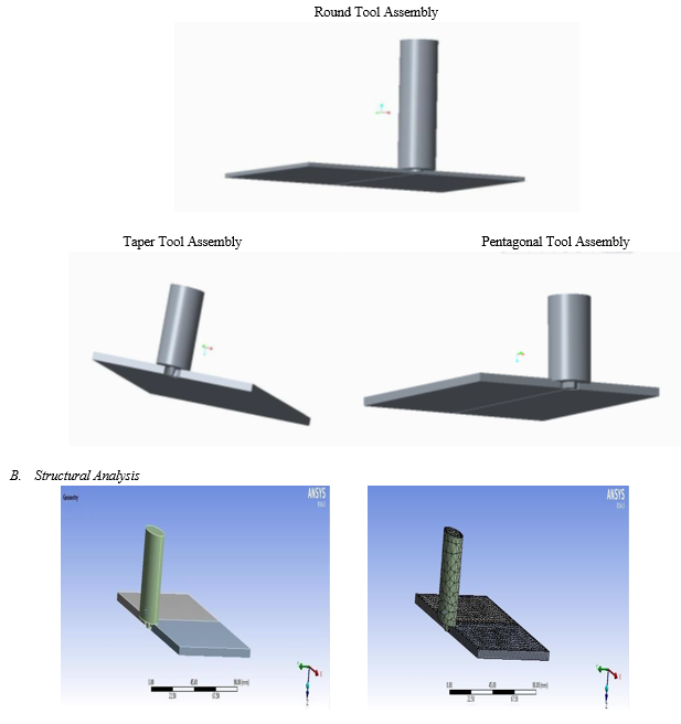
- The 3D modeling of FSW is designed.
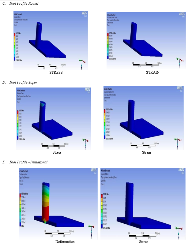
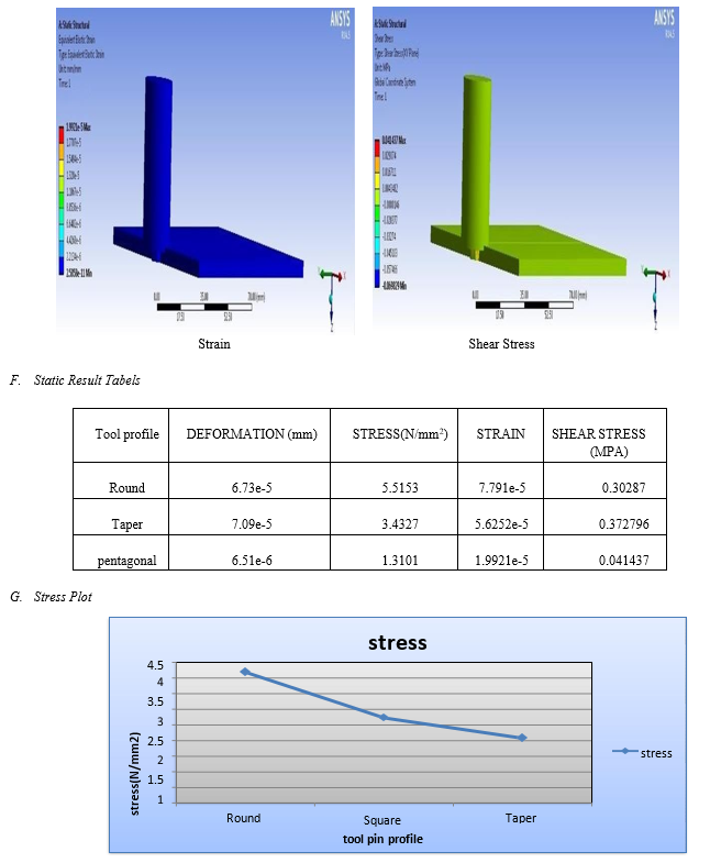
- In static analysis, to determine the stress, strain and deformation.
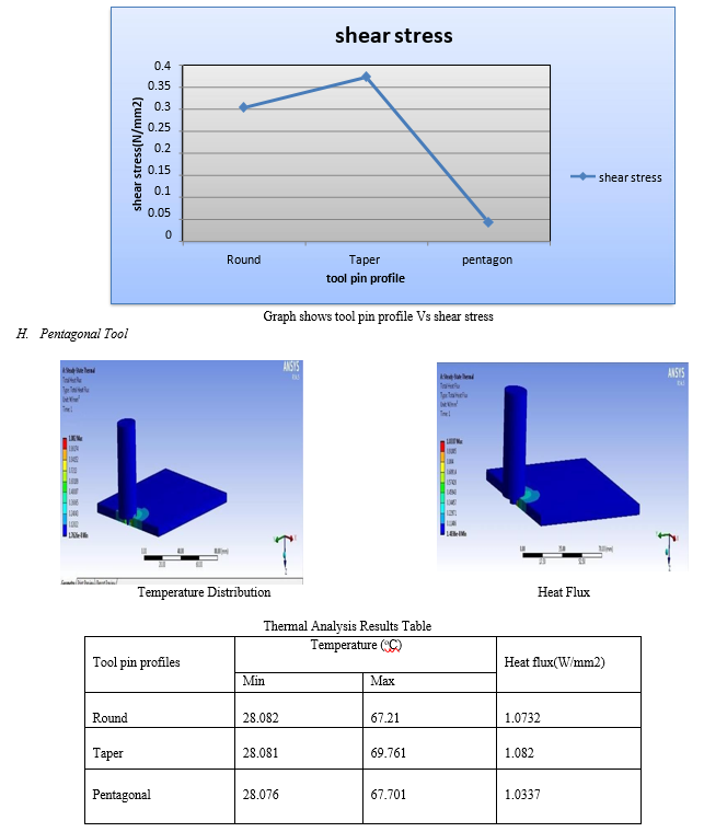
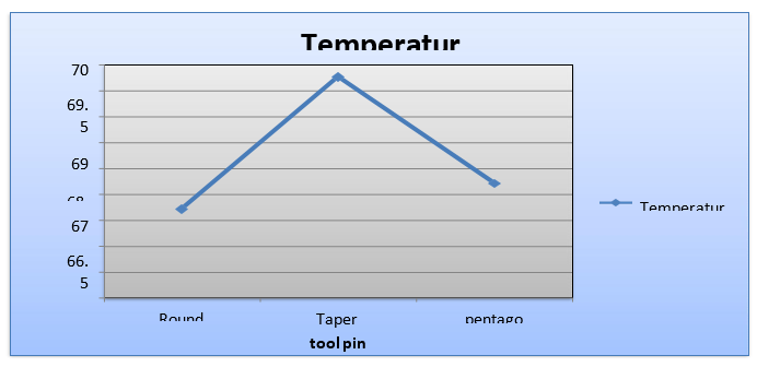
- In thermal analysis, to determine the temperature distribution and heat flux.
IV. MATERIALS AND RESPONSES
In this project we are taken work piece materials are aluminum alloy 5052 and aluminum alloy 6063 and tool material is HCHCr (High Carbon High Chromium steel)
A. AA5052
AA5052 has the same high resistance to general corrosion as other non heat treatable aluminium alloys. It also has the higher resistance to slightly alkaline conditions common to the 5000 series alloys. The resistance of 5052 to corrosion in marine atmospheres is excellent, exceeding that of 5005, hence the frequent use of 5052 in marine applications.
B. AA6063
AA6063 is an aluminum alloy with magnesium as the primary alloying element. Aluminium alloy 6063 is a medium strength alloy commonly referred to as an architectural alloy. It is normally used in intricate extrusions. It has a good surface finish, high corrosion resistance, is readily suited to welding and can be easily anodised.
C. HCHCr
D3 Steel Having 12 % ledeburite chromium tool steel with great wears resistance. Basically, utilized as cutting tools for sheets up to 4 mm thickness, trimming dies, blanking dies for paper and plastics, shear cutting edges and rotational shear edges for sheet thicknesses up to 2 mm.
D. Tensile Test
Tensile testing, which is also known as tension testing is a fundamental materials science and engineering test in which a sample is subjected to a controlled tension until it is a failure. Properties that are directly measured via a tensile test are ultimate tensile strength, breaking strength, maximum elongation and reduction in area. The following properties can also be determined: Young's modulus, Poisson's ratio, yield strength, and strain-hardening characteristics from these measurements
E. Brinell Hardness (BH) Test
Method of measuring the hardness of a material by pressing a chromium-steel or tungsten-carbide ball (commonly one centimeter or 0.4 inch in diameter) against the smooth material surface under standard test conditions (such as between 300 to 3000 kilograms of force for 5 to 30 seconds). Here the hardness is expressed as Brinell Hardness Number (BHN) which is computed by dividing the load in kilograms by the area of indentation that is made by the ball measured in square millimeters.
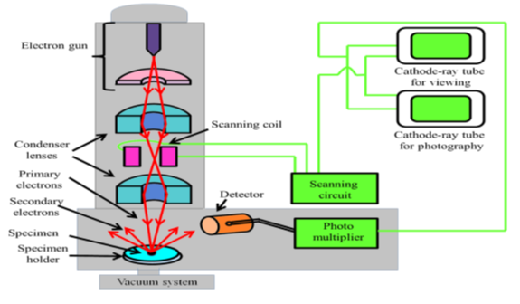
F. Scanning Electron Microscope (SEM)
A normal scanning electron microscope operates at a high vacuum. Here a beam of electrons is generated by a suitable source, typically a tungsten filament or a field emission gun is a basic principle. The electron beam is thoroughly accelerated through a high voltage (e.g.: 20 kV) and is passed through a system of apertures and electromagnetic lenses to produce a thin beam of electrons and then the beam scans the surface of the specimen by means of scan coils (like the spot in a cathode-ray tube "old-style “television).
V. MODELING AND SIMULATION
A. CREO
Creo is a family or suite of Computer-aided design (CAD) apps supporting product design for discrete manufacturers and is developed by PTC. The suite consists of apps, each delivering a distinct set of capabilities for a user role within product development.
Creo runs on Microsoft Windows and provides apps for 3D CAD parametric feature solid modeling, 3D direct modeling, 2D orthographic views, Finite Element Analysis and simulation, schematic design, technical illustrations, and viewing and visualization.
Creo Elements and Creo Parametric compete directly with CATIA, Siemens NX/Solid edge, and Solid Works. The Creo suite of apps replace and supersede PTC’s products formerly known as Pro/ENGINEER, Co create, and Product View. Creo has many different software package solutions and features. Creo Illustrate is a good example.
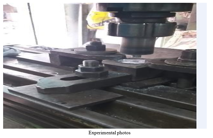
VI. EXPERIMENTAL INVESTIGATION
Experimental investigation is done to verify the mechanical properties of friction stir welding of aluminum alloy 5052 and AA 6063. The properties investigated are tensile strength, microstructure and hardness compared after welding.
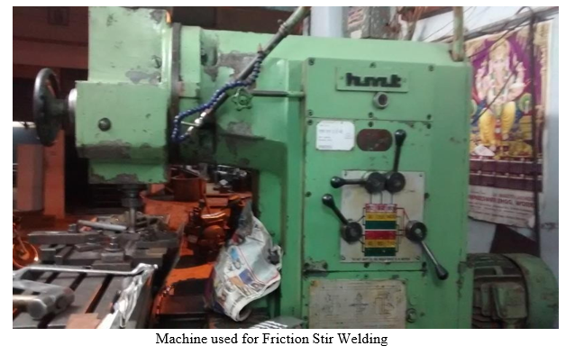
The welding is done on Vertical Milling machine.
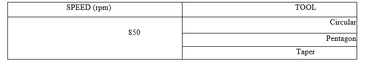
In this work, the process was done using a vertical milling machine having automatic feed. The tool rotational speeds and the feeds were set accordingly, and the respective experiments were conducted. The tool profiles considered as Circular, Pentagon and Taper.
VII. RESULTS AND DISCUSSIONS
A. Brinell Hardnesstest
The Brinell hardness test is carried out on the three samples and the results are furnished in belowTable. The ball shaped indenter made of hardened tungsten is used for this test. The load applied is 250 Kef. Brinell hardness test specimen in shown in fig. Fig. shows the hardness value of three samples. It can be noted that sample 2 has the maximum hardness followed by sample 1 ,2 and sample 3 in all the trials.
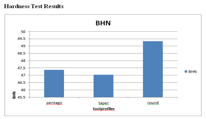
The hardness of the weld zone and composites was evaluated by using Hardness Testing Machine, Mitutoya, Japan of Model no HM113 with HV 0.05 load and diamond indenter is used. The indentation time for hardness measurement was 15 seconds. An average of three readings was taken for each hardness value. And were considered for plotting the graph as shown in Figure
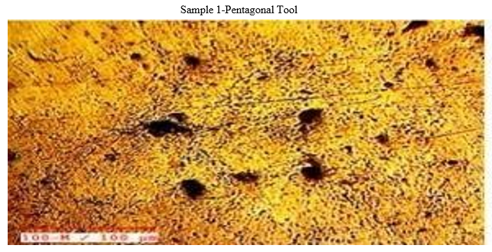
B. Tensile Test
Tensile testing, also known as tension testing, is a fundamental materials science and engineering test in which a sample is subjected to a controlled tension until failure. Properties that are directly measured via a tensile test are ultimate tensile strength, breaking strength, maximum elongation and reduction in area. From these measurements the following properties can also be determined: Young's modulus, Poisson's ratio, yield strength, and strain-hardening characteristics. Uniaxial tensile testing is the most commonly used for obtaining the mechanical characteristics of isotropic materials. Some materials use biaxial tensile testing.
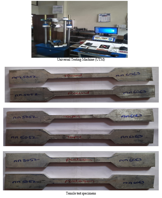
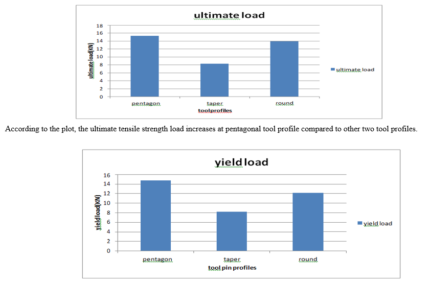
According to the plot, the yield strength load increases at pentagonal tool profile compared to other two tool profiles.
C. Metallographic Analysis
Metallographic weld specimens were cut, mounted, polished and examined by optical and scanning electron microscopy (SEM). SEM microscope used was a JEOL JSM-6460 equipped with Oxford Instruments INCA-350 energy-dispersive spectroscopy system.
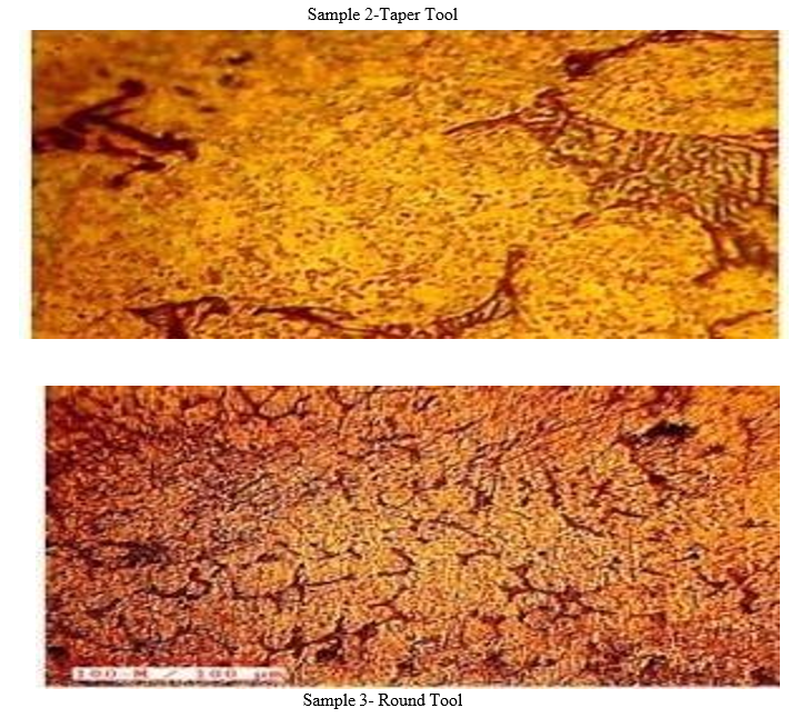
Micro structure of a prepared surface specimens to be tested by inverted metallurgical microscope range of 25X - 500X magnification. Micro structure of polished surface resulted cluster formation of reinforcement particles as shown in the sample 1. Clear identification of non-metallic particles distribution in between metallic particles resulted by etching process as shown in the sample -2. The formation of dendritic structure resulted by solidification process observed before heat treatment of weld zone.
Conclusion
In this project different tool pin profiles is designed for doing Friction Stir Welding of two dissimilar materials Aluminum alloy 5052 and AA6063 running at speeds 850rpm. Modeling is done in CREO. 1) Structural analysis is performed on the different tool pin profiles to verify the deformation and stresses. 2) Thermal analysis to determine the temperature distribution and heat flux. 3) By observing the static analysis results, stresses values are decreases at pentagonal tool pin profile. 4) By observing the thermal analysis, the temperature values reduces at pentagonal tool pin profile compared other tool pin profiles. 5) In this thesis, two plates of the Aluminum alloy 5052 and AA6063 are welded experimentally on a vertical milling machine using 850rpm speed for tool. Tensile strength, microstructure and hardness are evaluated after welding. 6) By observing the tensile test results, ultimate tensile strength values are increases by pentagonal tool pin profile. 7) By observing the hardness test results, hardness values are increases by pentagonal tool at weld zone. 8) So, it can be concluded the pentagonal tool pin profile is the better.
References
[1] Sadeesh P, VenkateshKannan M, Rajkumar V, Avinash P, Arivazhagan N, DDAjrXkGz1p2FHQMfZ6QaedHZbxtzt1TCb,“StudiesonfrictionstirweldingofAA2024 and AA 6060 dissimilar metals”, 7 th International conference on materials for advanced technology, 2014, pp.145–149. [2] Prakash Kumar Sahu and Sukhomay Pal, “Multiresponse optimization of process parameters in friction stir welded AM20 magnesium alloy by Taguchi grey relational analysis”, Journal of Magnesium and Alloys 3, 2015, pp. 36-46. [3] PankajNeog, Dharmendra Thakur and Pranav Kumar Pandey,” Optimization of Friction stir welding parameters in joining dissimilar aluminium alloys using SPSS and Taguchi”,JournalofBasicandAppliedEngineeringResearch(JBAER),Volume1,2014, pp. 25-27. [4] E. Fereiduni, M. Movahediand A.H. Kokabi, “Aluminum/steel joints made by an alternativefrictionstirspotweldingprocess”,JournalofMaterialsProcessingTechnology 224,2015, pp. 1–10. [5] Joon-Tae Yoo, Jong-Hoon Yoon, Kyung-Ju Min and Ho-Sung Lee, “Effect offriction stir welding process parameters on mechanical properties and macro structure of Al-Li alloy”, 2nd International Materials, Industrial, and Manufacturing Engineering Conference, MIMEC2015, 2015, pp.4-6. [6] RazaMoshwan, FarazilaYusof, M. A. Hassan and S. M. Rahmat, “Effect of tool rotational speed on force generation, microstructure and mechanical properties of friction stirweldedAl–Mg–Cr–Mn(AA5052-O)alloy”,MaterialsandDesign66,2015,pp.118– 128. [7] G.I. ShaikhandU.A.Dabade.“Experimentalinvestigationonfrictionstirweldingof dissimilar metals”, 5th National conference on “Recent Advances in Manufacturing (RAM-2015)”, 2015, pp.15-17. [8] Vinayak D. Yadav and Prof. S. G. Bhatwadekar, “Friction stir welding of dissimilar materials between AA6101 aluminium and pure Copper”, International Journal of Engineering Sciences & Research Technology, 2014, pp. 505-508. [9] S. Jambulingam, “Optimization of process parameters of FSW for dissimilar aluminiumalloysAA7050andAA3014”,InternationalJournalofEmergingResearchesin Engineering Science and Technology, volume-2,2015. [10] Shaikh Mohammed Shakil and Prof. Yagnesh B Chauhan “Optimization of friction stir welding process parameters for welding aluminum alloys”, International Journal of Science Technology & Engineering Volume, 2015, pp. 69-75. [11] A. Pradeep and S. Muthukumaran, “An analysis to optimize the process parameters offrictionstirweldedlowalloysteelplates”,InternationalJournalofEngineering,Science and Technology Volume 5, 2013, pp.25-35. [12] FeiZhang,XuekuanSu,ZiyongChenandZuorenNie,“Effectofweldingparameters on microstructure and mechanical properties of friction stir welded joints of a super high strength Al–Zn–Mg–Cu aluminum alloy”, Materials and Design 67, 2015, pp.483–491. [13] Olivier Lorrain, Veronique Favier, Hamid Zahrouni, Didier Lawrjaniec, Understanding the material flow path of friction stir welding process using unthreaded tools, Journal of Materials Processing Technology pp: 603-609,2010 [14] H.JLin.andH.Fuji,Mechanicalpropertiesoffrictionstirweldedjoinsof1050-H24 aluminum alloy, Science and technology of welding and joining, Vol.8, 2003, pp.50-54. [15] Y.H. Zhao, S. B Lin and F. X. Qu, The influence of pin geometry on bonding and mechanica lproperties in frictionstirwelded 2014alloy, materialletters,Vol.59,2005,pp. 2948- 2952. [16] Fujji Hidetoshi and Cri Ling., Effect of tool shape on mechanical properties and microstructure of friction stir welded aluminum alloys, journal of materials science and engineering, Vol.54, 2006, pp.25-31. [17] S.Benavides,Y.LI,L.E.Murr,D.BrownandJ.C.McClure,lowtemperaturefriction stir welding of 2024 Aluminum, Scripta Materialia, Vol.41, No.8, 1999, pp.809-815.
Copyright
Copyright © 2022 Jujavarapu Sai Ravendra, Palukuri Veerendra. This is an open access article distributed under the Creative Commons Attribution License, which permits unrestricted use, distribution, and reproduction in any medium, provided the original work is properly cited.

Download Paper
Paper Id : IJRASET41986
Publish Date : 2022-04-28
ISSN : 2321-9653
Publisher Name : IJRASET
DOI Link : Click Here
 Submit Paper Online